Quick Summary:
The Combined Charging System has become the most prominent solution for DC fast charging. In this blog, we have carefully analyzed everything necessary to adapt the EV charge controller – CCS2 for the Electric Vehicle market.
Table of Contents
Introduction
The Faster Adoption and Manufacturing of Hybrid and Electric Vehicles (FAME) scheme has induced a rapid movement in the Indian E-mobility segment. A total of 2877 EV charging stations are sanctioned in 68 cities across 25 States/UTs under the phase-II FAME India scheme.
More than 452 EV charging stations have been set up till now. The Ministry has been making sincere efforts to address solutions for the range anxiety amongst the EV owners and potential users. At the same time, the stakeholders in the E-mobility segment are aware of the future-proof solutions which will drive sustainable mobility solutions.
The adoption of the Combined Charging System is bringing the world closer in terms of fast-scaling the EV infrastructure. It is evident now that the J1772-compliant level 1 & 2 Electric Service Equipment (EVSE) has been implemented by building a CCS controller for fast DC charging.
Let’s discuss the working of a CCS2 controller in detail.
How does the EV Charge Controller - CCS2 work?

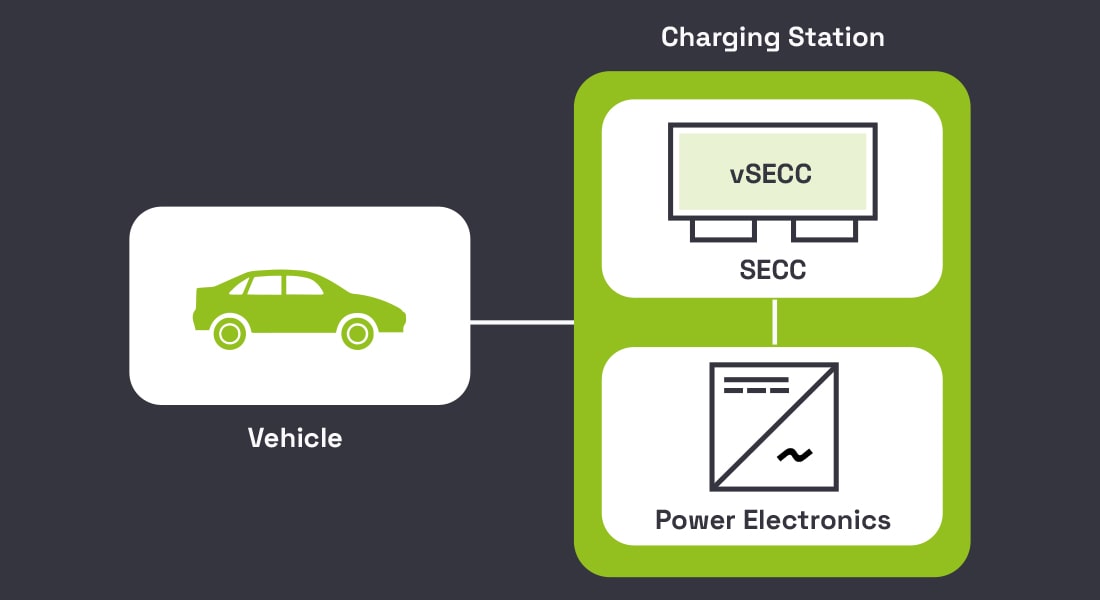
As you can see in the image above, is an overview of the main participants in the communication. The left block represents the vehicle to be charged, communicating with the charging station.
The charging station constitutes a Supply Equipment Communication Controller (SECC) connected with the Power Electronics grid. The SECC and Power Electronics together comprise of the EV charge controller.
The connection to the vehicle is based on Power Line Communication (PLC). However, before the PLC can be established between the vehicle and charging station, it is necessary to induce the vehicle and charging station to each other.
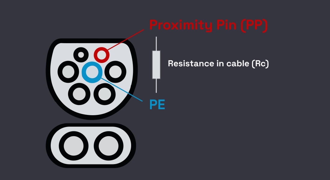
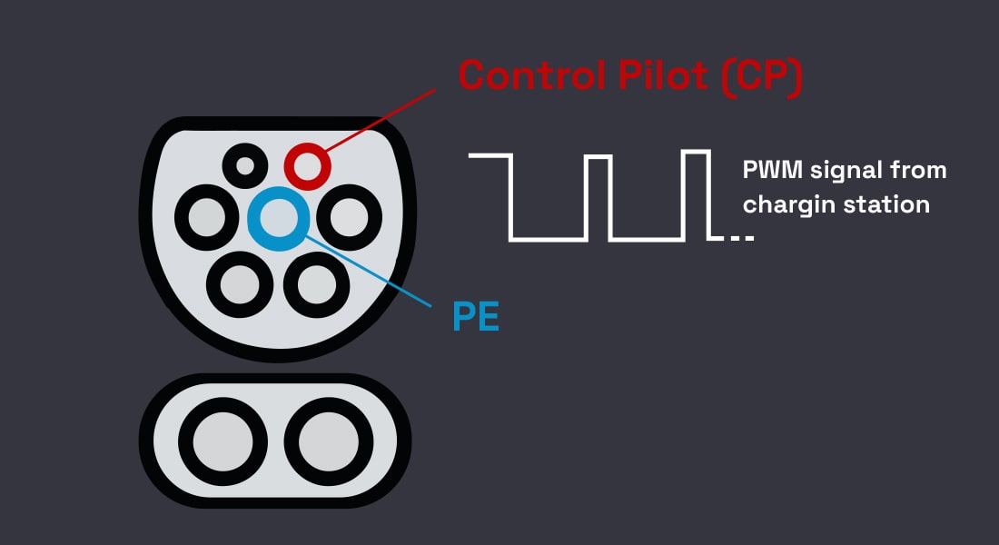
This is done with basic signaling, consisting of 2 communication pins:
Looking for a well-equipped CCS Controller to assist your EV charging infrastructure?
Check out bacancy’s EV charging controller with all necessary built-in features to future-proof your Electric Vehicle ecosystem
CCS2 Connector
- Proximity Pin (PP): Proximity Pin (PP) allows to communicate information of power of the used charging cable, and it uses a resistance coding. Both ends are coded to identify the maximum power transfer of the cable.

- Control Pilot (CP): The Control Pilot gives the option to limit the current and the power on the charging station section, which is based on a generated PWM signal. It is generated by the communication controller in the charging station. Now, based on the ratio of the positive and negative signals, i.e., the signal amplitude. The maximum usable power is set for the specific vehicle.

In the case of DC charging, the signaling pin is also relevant because it uses high-level communication protocol according to ISO 15118-2 and DIN 70121.
Let us now look at the charging sequence during DC charging.
Communication Sequence
For the purpose of understanding the charging sequence, let us look at the communication between the vehicle and the EV charging station.
1. Initialization
The charging sequence starts by plugging in the cable from the vehicle into the charging station. This initiates a transaction into the backend.
2. Authentication
Once the cable has been plugged in, it is now necessary to identify how to begin charging. This can be done by using RFID authorization by the driver.
The other way is through the Plug & Charge method, which is authorized centrally through certificates and ISO standards, without the driver’s interaction. By this means, the authorization takes place in the backend. If the authorization is approved, the charging will begin else;, the operation will be rejected.
3. Parametric check
Once the charging has been approved, the vehicle exchanges charge parameters. These could include the State of Charge of the battery or power limits, perhaps required departure time. In general, information on the required energy amount.
These charge parameters are also passed on the backend, and the backend monitors and controls the distribution to several charging stations.
4. Charging Profiles
The power manuals can generate one or several optimum charging profiles based on the charge parameters. These can then be offered to the vehicle by the communication control or the charging station.
5. Selected Profile
The vehicle itself can then select the charging profiles and signal it back to the charging station, which passes it to the backend. It is also possible that the vehicle generates its charging profile based on these optimum profiles.
This profile can also be reported back to the charging station. The pre-requisites are that the required power should always be below the maximum power that the offered charging profile supplies.
6. Meter values
Once all this information has been exchanged, the vehicle, charging station, and the backend have complied with the necessary. The actual power transfer can be initiated.
The EV charge controller exchanges certain limits, i.e., the minimum and the maximum current values the latter can supply.
Now, once the communication between these two participants is established, Power Electronics continuously signals the information of its state via a protocol. For instance, measured currents, voltage, and the isolation status. This procedure is done followed by an isolation check.
EV is not in the future anymore!
Bacancy is serving the E-mobility industry with future-ready EV solutions. Get in touch with the Leading Product Development Company
7. Isolation Check
The isolation check measures the isolation of DC+ and DC- to the ground. This is done to eliminate an isolation fault in the high voltage system. The isolation check also requires a validation status. It means the isolation has been checked and reported ‘ok’ back to the communication controller.
8. Pre-charge Phase
The Supply Equipment can now initiate the precharge phase. During this phase, the voltage demanded by the vehicle is put on the intermediate circuit.
As soon as this has been reached, the vehicle closes its contact and establishes the connection between Power Electronics and the vehicle’s battery pack.
9. Charge Phase
Once the precharge phase is over, the connection has been established. The actual power transfer is executed in the charging loop. The charging loop includes the vehicle to transmit all the target values of voltage and current in cycles to the communication controller.
The communication controller passes on the required values to the Power Electronics and gives feedback to the vehicle’s current state. This procedure continues until the battery has been fully charged or until the user or the backend stops the charging procedure.
10. Post Charge Phase
In this phase, the current is reduced so much that the connectors of the vehicle can be closed without being under load. Optionally, the vehicle can contact so-called welding detection. During this detection, it checks the open contact so that the charging cable can be disconnected safely.

Combined Charging System Protocol & Standards
An Electric Vehicle Supply Equipment (EVSE) should have the bandwidth to handle different types of EVs. Different EVs have sophisticated AC/DC charging requirements, time taken in charging, and power supplied. Here are the most important standards created to standardize the communication from EV to EVSE and processes for charging requirements.
SAE J1772 establishes a regulation for multiple charging stations, framed by the Society of Automotive Engineering (SAE). It manages the requirements for handling an Alternating Current (AC) charge using the PWM (Pulse Width Modulation) waveform of the control pilot signal in the EV-EVSE interface. Moreover, SAE J1772 defines the sequence and timing of Vehicle-To-Grid (V2G) messages based on DIN SPEC 70121.
DIN SPEC 70121 regulates HLC (High-Level Communication) over Pilot signal between EVSE and EV in a DC charging session. The North America and European regions had employed Power Line Communication (PLC) before DIN 70121 was known.
ISO 15118 is a comprehensive standard and deals with the security of High-Level Communication for both AC and DC charging sessions. It comprises of two identification methods for charging:
A. External Identification Mode (EIM): It is an identification method before initiating the charging process, wherein the driver needs to manually use an identification method, similar to DIN SPEC 70121 or SAE J2847.
B. Plug and Charge Mode(PnC): In this mode, the ISO 15118 enables scheduling the charging process based on energy cost and grid capacity. The necessary information for billing and identification is automatically swapped via HLC between the EVSE and EV.
Features of CCS2 Controller for Indian Electric Vehicle Market
- IOS/IEC 15118 and DIN 70121 compliant
- RFID / PnC Authentication support
- HMI (Human Machine Interface) support
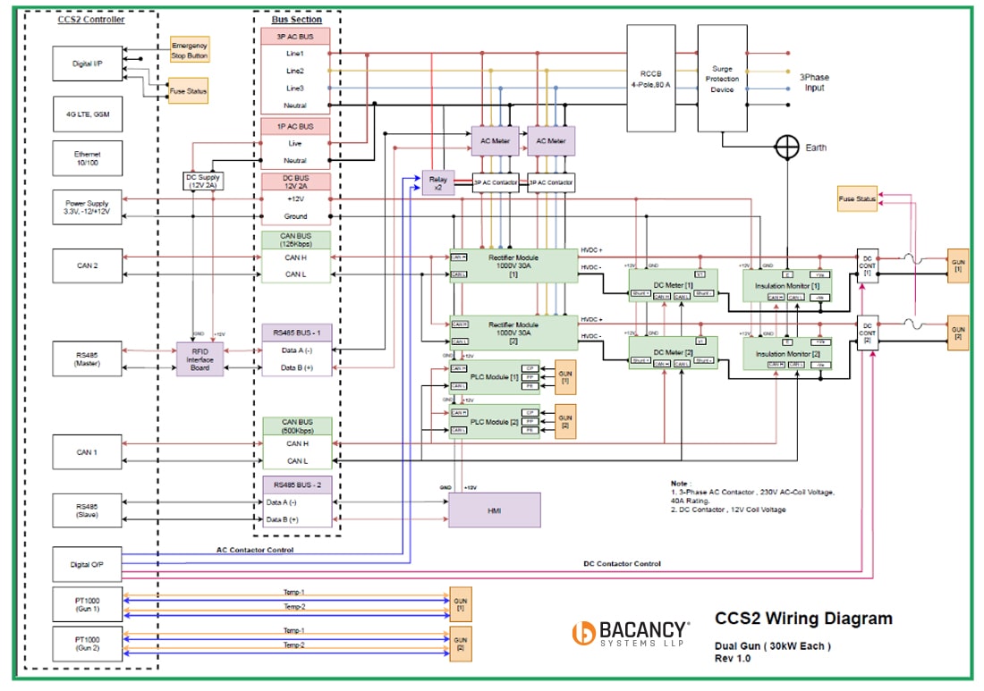
- CAN enabled interface for Power Module Integration
- Single & Dual GUN support
- Fit for 30kW, 60kW, 120kW rating
- OCPP1.6 support
- 4G enabled, Ethernet-10/100, Wifi for Network Connectivity
Wrap Up
That was all about the EV charge controller – CCS2 for electric vehicle market. By now, you would have been familiar with the CCS2 standard, how it works, the ISO/DIN compliance, and its features. Undoubtedly, the CCS2CON is the most viable and technically innovative solution for facilitating communication between the Electric Vehicle Supply Equipment and the electric vehicle.
Bacancy’s extended venture Bacancy Systems is a leading product engineering and embedded company recognized for its cutting-edge hardware and embedded solutions innovation.
Frequently Asked Questions (FAQs)
J1772 is the official Japanese standard. The EV charge connector includes the high-speed charging pins with the J1772 connector.It uses the J1772 charging inlet and combines two more pins.
The plug-in EVs like the Chevy Volt, Nissan LEAF, Tesla Model S use the SAE J1772 standard to charge and connect.
A 50KW charger will facilitate the rapid charging speed. In 20 to 60 minutes, an electric car will be fully charged, depending on the battery size and the State Of Charge before initiating the charging process.
The Level 3 and Level 4 charging stations represent the most advanced EV charging and a shift from the type of electricity used in our daily household applications. This charger type is the fastest amongst the three and can replenish up to 80% within 30 minutes.
Your Success Is Guaranteed !
We accelerate the release of digital product and guaranteed their success
We Use Slack, Jira & GitHub for Accurate Deployment and Effective Communication.


